1958 / Analog game
 Tennis for Two
Tennis on an analog computer
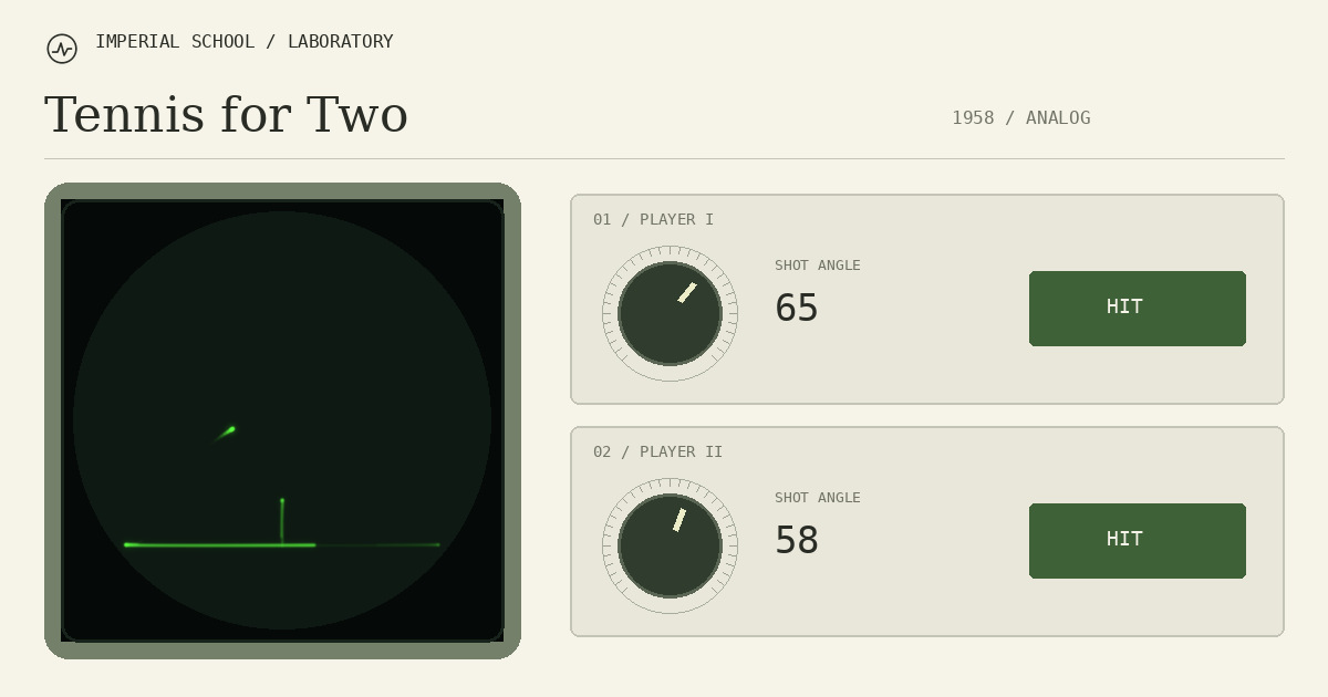
Two round knobs, two buttons and a ball on an oscilloscope. An electrical Tennis for Two model in ngspice/WebAssembly.
- Original
- 1958
- Location
- Brookhaven National Laboratory, USA
- Hardware
- Donner analog computer, oscilloscope and two handheld controllers
- Players
- 1–2 players · watch mode
- Our version
- 0.8.8
- Status
- One SPICE instrument: computer, transistor switch and screen model
A ball computed by a circuit
In 1958, visitors to Brookhaven could play tennis on an oscilloscope. William Higinbotham conceived the game and Robert Dvorak helped build it. The screen showed the ground, net and a luminous ball; each player had a separate controller.
Analog-computer output voltages set ball position. Integrator capacitors stored charge and relays reconfigured the circuit at hits and collisions. We reconstruct both the game and the way its hardware calculated motion.
How to hit, and where the racket is
There is no visible racket. Pressing the button starts a new flight from the ball’s current position. The round knob changes a coupled pair of potentiometers, selecting a low, fast shot or a higher trajectory.
Start with the lit Serve button. After the ball crosses the net, the opponent’s button lights up. You may hit on your side immediately after the crossing or after a bounce. The knob pointer shows the selected angle.
Keyboard commands work while the instrument has focus: click the screen or knob. A/D adjust the left angle; ←/→ adjust the right. Letter commands use physical key codes and also work with a Russian keyboard layout. The hit uses the angle already selected.
Choose a mode: Me and Opponent — two people; Me and Fox — a person on the left and the Fox CPU on the right; Gremlin vs Fox — two automatic controllers. Changing mode starts a new rally. Automatic knob movements and presses are visible; manual control of those controllers is disabled. P and the pause button work in every mode.
- Left player: A / D — knob; W or space — hit.
- Right player: ← / → — knob; ↑ — hit.
- Mouse or touch: drag the knob by its centre or rotate around the rim, then press Hit.
- For keyboard control, click the instrument first. P — pause.
Sources [2]
Controller mechanics
Mechanics is enabled by default. Knobs have inertia, friction and small coupling play; buttons have travel, return springs and a closure threshold. The instrument switch enables direct input while preserving the rally.
Rotational resistance is compared with compact General Radio potentiometers from 1955. A calculated two-section proxy is selected. Button parameters and knob dynamics are distinguished from comparator specifications. Planck.js, based on Box2D, solves controller mechanics; ngspice continues solving the electrical instrument.
Our addition: Gremlin and Fox CPU operators
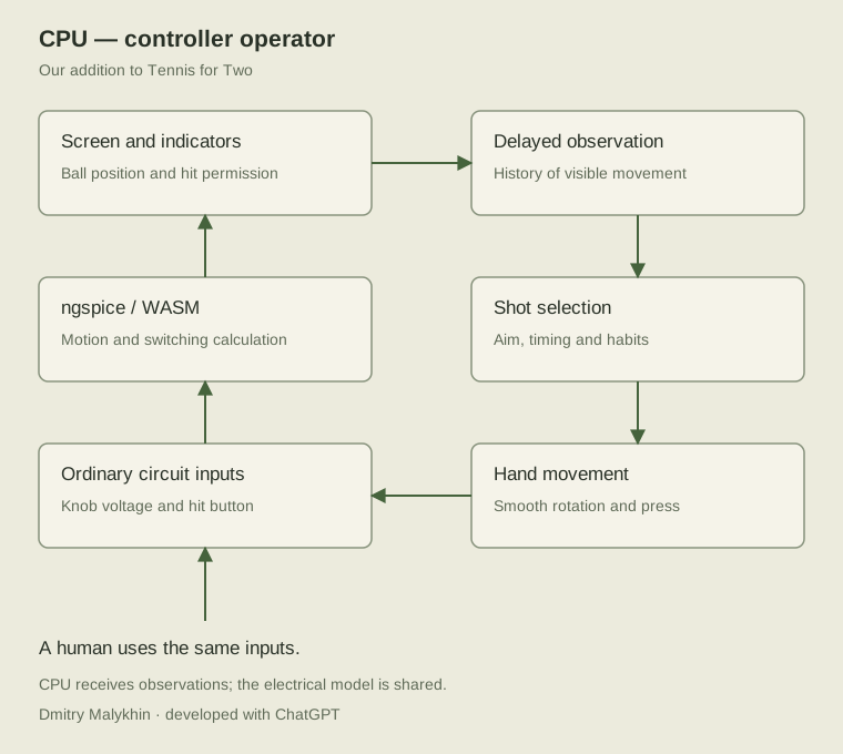
The automatic player sits above the electrical circuit and uses its ordinary controller. It receives delayed observations of the ball and visible hit permissions. Motion is estimated from earlier positions; future trajectories and instantaneous internal velocity outputs are not exposed.
Gremlin tends to hit earlier and lower. Fox prefers deeper reception and a higher return. These are our invented playing habits; all controllers share the same physical capabilities and circuit inputs.
Studies of moving-target interception and rotary controls support separating decision delay from hand-movement duration. Our profile uses 200–300 ms delays, with rotation time depending on distance and precision. The knob accelerates and stops smoothly, with a maximum speed of 60% of its range per second. Parameters are open for human gameplay comparison.
Pause freezes game time and operators. In watch mode, they serve automatically after a rally. Changing mode clears earlier decisions and observations. Eight checks include two CPUs on actual WASM and returns against ordinary manual button commands.
Scroll the table horizontally →
| Mode | Left controller | Right controller |
|---|---|---|
| Me and Opponent | Human | Human |
| Me and Fox | Human | CPU · Fox |
| Gremlin vs Fox | CPU · Gremlin | CPU · Fox |
Demo: recorded simulation
Demo is an additional mode, off by default. A precomputed 15.17-second recording loops at 1.00×. Low closing returns lead to the next serve; ball and control positions match across the boundary.
The electrical circuit, CPU decisions and mechanical controls are recorded losslessly, with mechanics enabled. The browser calculates beam, phosphor and glass optics. Glass and language switches retain playback position. About 21.9 MB load only when Demo is selected.
Peter Takacs and Brookhaven’s hardware restorations
We also draw on Peter Takacs’s restoration team. The project began for the laboratory’s 50th anniversary in 1997. Takacs, Gene Von Achen, Paul O’Connor and Scott Coburn took part in the game’s anniversary demonstration on 24 October 2008. BNL describes mechanical relays and germanium transistors with a modern integrated analog replacement for the tube computer.
In his account of 14 December 2010, Takacs described semiconductor op-amp damage from relay-switching transients. The team was preparing to connect a restored Donner Model 3400. This is a separate project stage and computer model, retained as distinct from the original Model 30.
This experience motivates electrical investigation of switching transients. Protective components introduced for modern amplifiers must be distinguished from original connections. Our diodes, coil parameters and amplifier limits are declared C01 assumptions; Takacs’s publications do not measure those coefficients.
BNL’s explanation quotes Takacs’s 36 Hz display-switching figure. Our switch and computer share one circuit; the separate switch bench produces approximately 39.09 Hz per full cycle. Comparing these figures is an interpretation. The 200 Hz controller exchange and browser frame rate describe other layers.
Why reconstruct the electrical circuit
This began as tennis on a 404 page. We then asked why the ball should move that way, and chose to reconstruct how the game calculated motion: stored capacitor charge, switched networks and measurable amplifier outputs.
ngspice 45.2 evaluates the SPICE model in WebAssembly. We wrote the circuit profile, continuous-session control, electrical-state transfer, controller UI and checks. JavaScript supplies input signals and reads results; collisions are calculated by the circuit.
The project has three website views: the compact 404 game, a standalone playable instrument and this research page. Here we document the source of connections and parameters, our changes and the checks behind the result.
How our instrument works
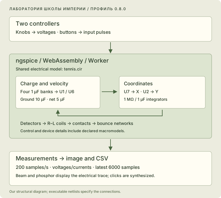
Knobs set coupled charge voltages. Contacts connect selected banks to velocity-amplifier feedback. Subsequent stages integrate those voltages: U7 gives X, U2 the vertical coordinate relative to net top.
The same ngspice session evaluates all 15 display-switch PNP transistors. Computer outputs connect directly to switch inputs. Display loading, its passive supply and the finite resistance of line sources participate in the common electrical calculation.
An input/amplifier oscilloscope macromodel follows the switch. Plate-voltage and beam-current traces feed the woscope-derived renderer. Phosphor accumulates and decays according to circuit time. WebGL2 is used when required extensions exist; CPU fallback calculates the same model.
The game exchanges controller state every 5 ms of circuit time. Adaptive beam points retain their actual timestamps. Periodic checkpoints transfer capacitor states from computer, transistor network, supply and scope, plus coil currents. Integration-history restart error is measured separately.
Two surviving drawings
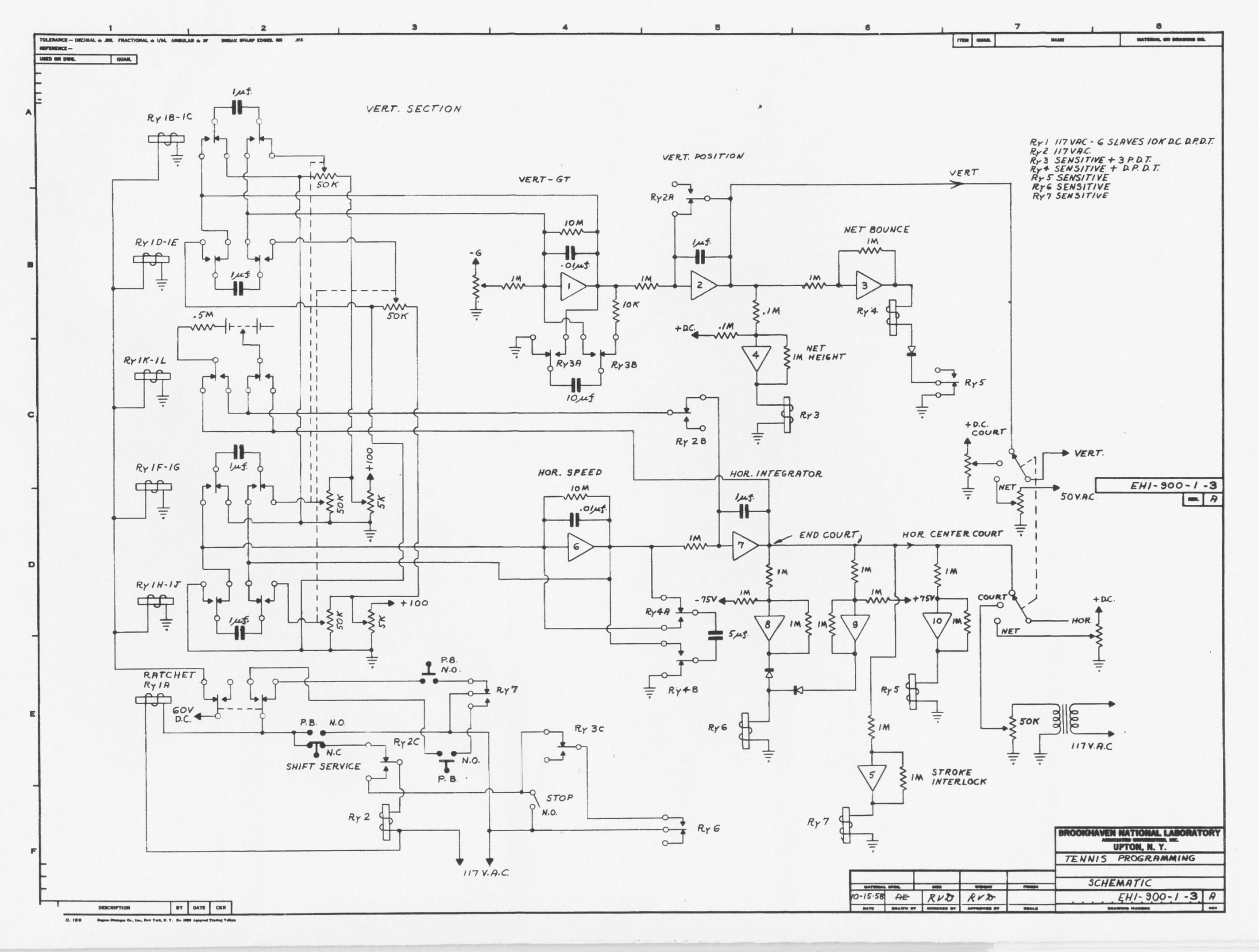
The main source is Brookhaven’s published Tennis Programming, EH 1-900-1-3, revision A, dated 15 October 1958. It supplies computing networks, values and switching. Open the original-resolution image to inspect individual connections.
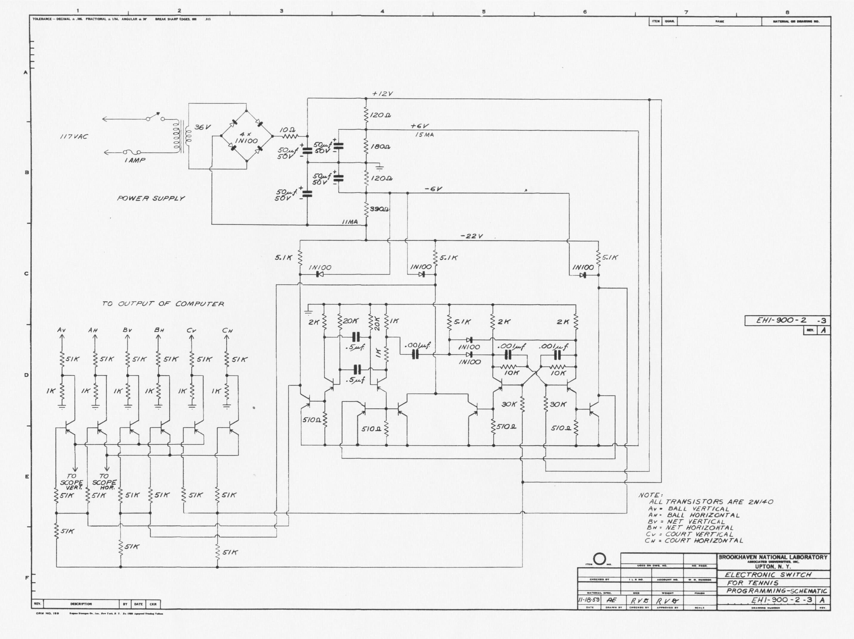
Electronic Switch for Tennis Programming, EH 1-900-2-3, revision A, dated 18 November 1959, describes display commutation. It identifies 2N140 transistors and separate vertical/horizontal inputs for ball, net and court. Its oscillator and keys operate in the joined game analysis, with a passive supply and loaded line controls. A separate bench is also provided.
The drawing dates remain distinct from the game’s first demonstration. Archival images retain their rights and Brookhaven attribution; our code’s license does not relicense them.
Reconstruction status
The computer, display-switch supply, loaded line regulators, all 15 transistors and scope macromodel run in one transient analysis. Amplifiers and relays use declared equivalents.
Scroll the table horizontally →
| Section | Implementation | Evidence and choices |
|---|---|---|
| Charge banks | Four 1 µF capacitors, charging through 50 kΩ, switched into feedback | Topology from the archival drawing; knob transfer curves calibrated by us |
| Computing networks | U1/U2 and U6/U7; 1 MΩ /1 µF, 10 MΩ ∥0.01 µF branches | Published values; finite amplifier macromodels |
| Ground and net | Reconnection of 10 µF and 5 µF holding capacitors | Electrical bounce; some control logic uses equivalents |
| Relays and contacts | R–L coils, diodes, actuation delay and finite contact conductance | Engineering macromodels |
| Controllers | Round knobs, buttons, keyboard, touch and hit permission | Working UI; functional interlock equivalent |
| Measurements | Voltages, currents, CSV, model JSON and executable SPICE | Outputs of the current model |
| Display and sound | Transistor X–Y chain, scope model, Gaussian beam, phosphor and synthesized clicks | Declared CRT and sound parameters |
| Supply and lines | Bridge, divider, filters, loaded potentiometers and common 60 Hz phase | Archival topology with declared parasitics, offsets and regulator settings |
Our decisions and substitutions
For each substitution we record what changed, why and its status. These are our reconstruction decisions, kept separate from historical assembly corrections.
The amplifier has finite gain, bandwidth, output resistance and rail limits. The relay coil retains current after disconnection and contacts change conductance smoothly. These calculate the chosen model’s transients.
Scroll the table horizontally →
| Entry | Decision |
|---|---|
| C01 · Amplifiers and relays | Open macromodels for unavailable detailed component behavior. |
| C02 · Court ends | Symmetric comparators and diode combination for U8/U9 behavior. |
| C03 · Net | Symmetric RC center-crossing detector, documented profile addition. |
| C04 · Hit interlock | Electrical state memory and behavioral comparisons. |
| C05 · Calibration | −60 V reference, 20 V net, ±62 V serve positions and explicit knob ranges. |
| C06 · Calculation | Finite input transitions, adaptive Gear and C/L state transfer. |
| C07 · Display and sound | Joined electrical chain with declared CRT model and synthesized sound. |
How we check the result
The computing profile passes 15 checks. Simple RC and R–L networks are compared with analytical solutions; a switched capacitor with charge redistribution. Rally, interlocks, bounces, serve changes, continuity and state transfer are then exercised.
We built native ngspice from the official 45.2 archive and compared it with WASM on the same circuit and inputs. This checks execution of the selected model. Source interpretation is reviewed separately.
Browser checks cover WASM loading, knobs, pause, full view, lazy 404 launch and CSV/JSON exports from an iframe. Narrow rendering was tested at 390 px; this is a viewport test. Click sounds are synthesized.
Profile 0.3.1 refined solver tolerances after a long automatic rally without changing topology or component values. Against the older strict settings on identical inputs over 3.2 s, maximum X/Y difference was 0.304 mV. All 15 computer checks and the CPU operator checks passed again.
Joined-circuit checks cover accepted beam points, phase/Worker transfer, memory, native comparison and image generation. Edge maxima and settled sections are reported separately. GPU/M1 checks are outstanding; full results and failed criteria are retained in the report.
Scroll the table horizontally →
| Comparison | Result | Conditions |
|---|---|---|
| Native ngspice ↔ WASM: X | ≤35.53 µV | Identical circuit and inputs; 3000 samples over 3 s |
| Native ngspice ↔ WASM: Y | ≤33.45 µV | Maximum coordinate-output difference |
| Seven C/L transfers | ≤37.99 µV in coordinates | Active rally against uninterrupted calculation |
| 1 ms ↔0.5 ms maximum step | ≤4.23 mV in coordinates | Convergence check on the same rally |
| Continuous ↔ sliced transient | ≤0.186 mV | Identical sources and netlist |
| Saved-history window | 66 s of game time, two transfers | 5720 saved points after the second transfer; total WASM memory not measured |
| Earlier strict ↔ stable tolerances | ≤0.305 mV in coordinates | Identical sources, 3.2 s and same netlist |
What we built together
Project author: Dmitry Malykhin, Gremlin. The laboratory concept, historical goals, decision to simulate electrical networks and controller requirements developed through our work on the game. Development in dialogue with ChatGPT (OpenAI) covers research, circuit modeling, code, tests and documentation.
Our work includes the computing netlist, continuous ngspice Worker, electrical-state transfer, round controllers, engineering panel, measurement exports and numerical checks. Three play modes add distinct CPU personas, reaction/movement models and automatic serving. The computer and switch feed the scope model; beam and phosphor consume the actual SPICE time trace.
External foundations include Higinbotham and Dvorak’s game, Brookhaven’s archive, published reconstructions, ngspice, EEcircuit’s WASM work and woscope. Their authors, sources and licenses are credited. We did not write the ngspice solver.
Scroll the table horizontally →
| Area | Result |
|---|---|
| Electrical model | Executable circuits, component parameters and substitution/evidence register. |
| Continuous calculation | One analysis for computer, supply, 15 PNP and scope; state transfer and Worker memory management. |
| Numerical core | Our expression-evaluation changes and comparative measurements within ngspice. |
| Controllers and operators | Round knobs and buttons, three modes, bounded CPU reaction and movement. |
| Display | woscope beam adapted to SPICE current/time, GPU/CPU phosphor accumulation and decay. |
| Research | Archival schematics, assumptions, open source, numerical checks and a full bilingual report. |
Electronic display switch: 15 transistors in SPICE
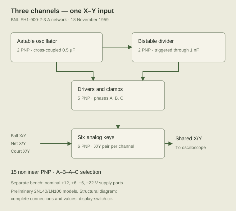
The switch follows the 1959 oscillator, divider, drivers and six analog keys. All 15 PNP transistors are evaluated electrically. The circuit alternates ball, net and ground channels.
In the game it connects directly to the ball computer. The separate bench measures frequency, transfer, channel isolation and parameter sensitivity with fixed ball inputs.
The original separate model gives approximately 39.09 Hz per full cycle. Takacs’s 36 Hz is retained as a historical comparison. Ge-device parameters remain preliminary. The working game includes transformer, bridge, divider, filters and loaded line regulators in the common simulation. The 60 Hz line excitation is an explicit setting.
The screen receives the beam trace
Inside the glass, a single electrical trace creates the image. The game sends X/Y plate voltages and beam current. Signal commutation produces the ball, net and ground.
The beam uses Igor Null and Chad von Nau’s woscope analytical moving-Gaussian integral. We added irregular SPICE timestamps, physical deflection scale, linear phosphor accumulation and shared CPU/WebGL2 equations.
Pause, hints and diagnostics stay on the external panel. Spot, two-component decay and exposure parameters are published reconstruction settings. Generic RCA P1 data supplies the declared persistence reference.
Screen glass optics
The Glass optics switch enables refraction, Fresnel reflection, absorption and one internal round trip. It is on by default; switching preserves the circuit and accumulated phosphor.
DuMont specifies a flat face for the 5ADP family used for our screen calibration. Thickness, optical index and room lighting are declared equivalents. Period sources and other reconstructions are compared in the research.
Our numerical contribution: prepared expressions
Version 0.5.1 reused common subexpressions within a solver evaluation and reduced WASM wrapper work. Version 0.5.2 prepares expressions and derivatives as operation sequences. Circuit equations, values, double precision and tolerances are retained.
Five builds were compared. O3 with the prepared evaluator reduced median execution time for the same bench from 6.61 to 5.32 seconds in Node/WASM and 6.53 to 5.50 in a Chrome Worker. Each had three repeats; all 69 signals matched.
The release passed 32 game checks, nine SPICE integration scenarios and 100401 bitwise evaluator comparisons. Cases include conditional branches, PWL, ddt, gmin, time, temperature, frequency and circuit recreation. These are measurements of the published test environments; M1 benchmarking remains separate.
Adopted reconstruction choices
The working release uses surviving primary schematics, published parameters and declared equivalents. The transistor supply and loaded line regulators participate in the common calculation.
A complete Model 3000 amplifier drawing is available. Takacs’s published reconstructions used modern op-amps and later a Model 3400. These are kept distinct from Model 30. The game retains checked finite amplifier and relay macromodels.
- Ge-device reverse and switching characteristics remain preliminary.
- Winding parameters, ESR and line-source settings are identified as calibration choices.
- Tube stages and high-voltage scope supply use a macromodel; generic P1 is the persistence reference.
- Numerical results belong to the declared scenarios. Mac M1/Firefox and hardware WebGL measurements remain separate checks.
Open the model and reproduce the checks
The research, schematics and current PDFs are available here. Project sources and releases are published on GitHub.
Open development
malyhind/tennis-for-two · MIT
- Installed on this site
- 0.8.8
- Latest GitHub release
- 0.8.8
- Published
Stars: 1 · Forks: 0 · Open issues: 0
Sources and materials
- Brookhaven: history of Tennis for Two ↗
- William Higinbotham’s notes ↗
- Tennis Programming archival schematic, 1958 ↗
- BNL: Electronic Switch for Tennis Programming, EH 1-900-2-3 A, 18 November 1959 ↗
- Angel De La Cruz and John Ryan: analog reconstruction, MIT, 2016 ↗
- MEGA: T42 reconstruction ↗
- ngspice: official solver documentation ↗
- EEcircuit-engine: wrapper source and WASM build ↗
- BNL, 3 November 2008: Peter Takacs’s anniversary reconstruction ↗
- Peter Takacs, 14 December 2010: Resurrecting One of the World’s 1st Video Games ↗
- RCA Transistor Manual SC-11, 1964: 2N140, printed p.131 ↗
- Igor Null and Chad von Nau: woscope beam algorithm and MIT code ↗
- MAME: vector CRT renderer architecture ↗
- DuMont Oscillographer, January–March 1953: 304-A tube and specifications ↗
- Planck.js / Box2D — Erin Catto, Ali Shakiba, MIT ↗
- General Radio Experimenter, January 1955, 970-series controls ↗
- MICRO SWITCH 1PB81-T2 advertisement, Electronic Design, 1 August 1957 ↗
- DuMont 5ADP flat-face CRT manufacturer data, printed p.48 ↗
- A. E. Martin, R. M. Bowie, Sylvania: Electronics, August 1950, p.110 ↗
- Pharr, Jakob, Humphreys: Physically Based Rendering, 4e, dielectric optics ↗
Reconstruction: · Version 0.8.8 ·